Some time ago I was searching a touch display for a project of mine. The requirements were 7 inch in size, capacitive touch digitizer and at least a resolution of 800x480px. I figured out Waveshare’s “7 inch HDMI LCD (B)” would be the perfect match. And I was thrilled that not only it was not only relatively cheap, but they got it right and (so the claim) implemented “fully valid” HID protocol (their shop still states “When work as a computer monitor, supports Windows 10/8.1/8/7, five-points touch, and driver free”).
When I received the display, everything was working out of the box with my Raspberry Pi 2 running on Windows 10 IoT. Then the Anniversary Update came and that’s when things got weird. Over-night my slightly laggy touch display turned into one that responded to scroll movements, but I could hardly get a “click” to trigger. Later I found that thread over at the MSDN support forums: Waveshare 7 inch display doesnt work on windows 10 iot core
After a few days of discussion Microsoft acknowledged that there was some change in the HID report processing pipeline, which now discards HID reports that are malformed. The advice was to contact Waveshare to see what they could do about the issue. Long story short, I never got a satisfying answer. So I decided to fix it on my own.
Analyzing the hardware
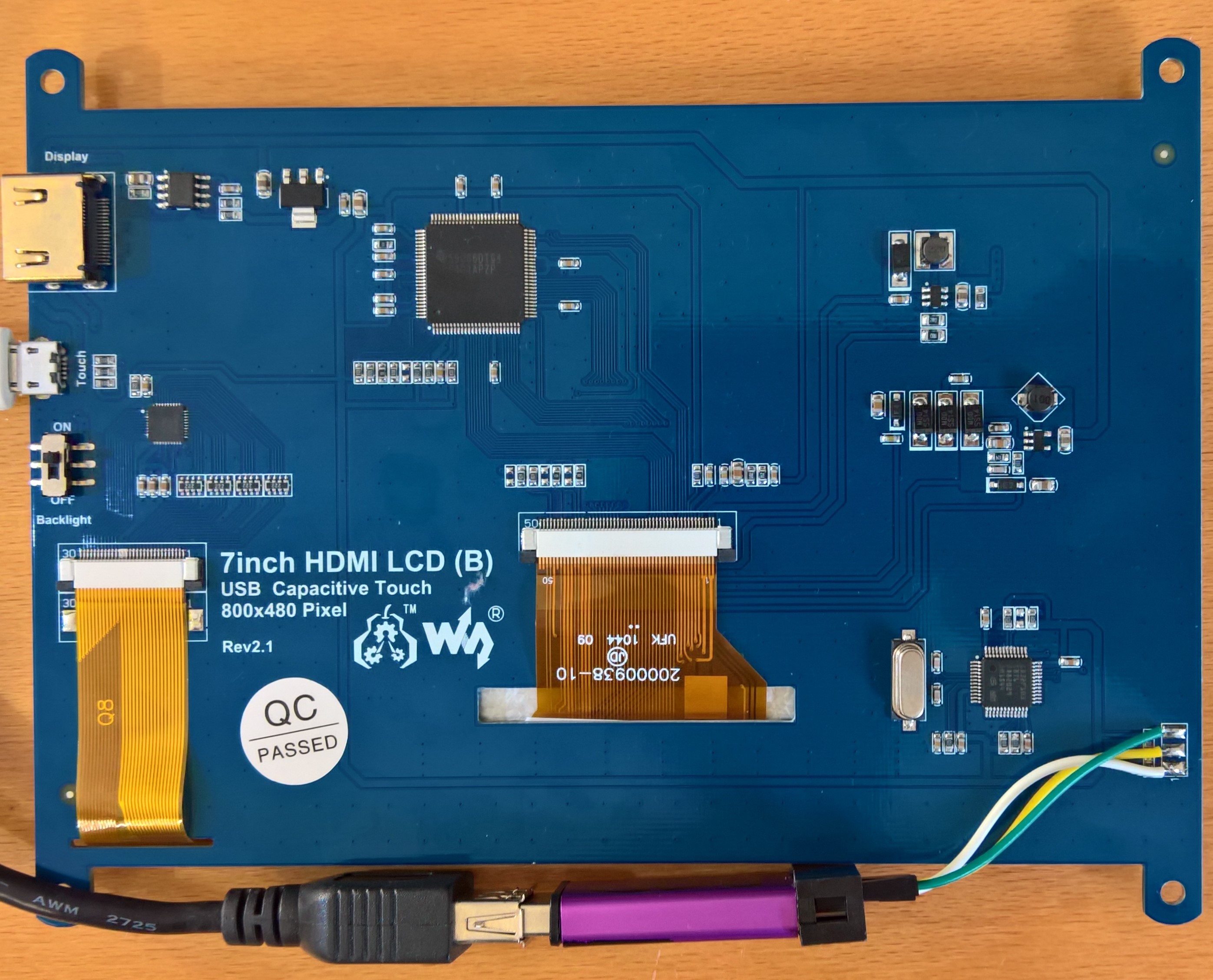
In the picture above you see the touch display’s PCB (with a STLink v2 clone attached).
The big chip in the upper half is a Texas Instrument TFP401APZP LCD driver, which, while being an interesting piece of hardware, isn’t relevant to this post.
On the left side, mid-PCB, you can see a 40 pin QFN package which turned out to be a touch screen digitizer chip made by Goodix, more specifically a GT811. Whilst I was unable to find a datasheet in a language I understand, I found a Chinese copy that I could Google-Translate in parts. It wasn’t fun, but enough to understand it’s connected via I2C to the micro-controller and to get a register map of the chip.
Last but not least there’s a GD32F103 dubbed chip in the right bottom corner of the board, which turned out to be a pin and (mostly) register-compatible replacement for ST’s STM32F103 Cortex M3 micro-controller.
After a few hours of probing and trace-following the boards, here’s the important stuff:
- MCU: GD32F103
- HSE connected to 8 MHz crystal
- USB (PA11/DA- and PA12/DA+) conntected to the micro-USB plug, with DA+ pulled high with an on-board 1.5k resistor (thus not software-resettable)
- GT811 connected on I2C2 (PB10 / SLC and PB11 / SDA) with 10k pull-up resistors on board
- GT811 /Interrupt pin connected to PB6
- SWD port broken out as PCB contact surfaces, on the bottom right (from top to bottom)
- SWDIO
- SWCLK
- GND
- Touch controller: GT811
- /Reset pin tied high via a 10k resistor
Software requirements
Basically the mode of operation of a touch display controller is pretty simple; step one is reading data from the touch digitizer and then sending it to the host device in a legible format. So far so easy. Well, mostly ;) There are a few hoops to get through!
Discovering the USB HID specification
Whilst I already had the joy to implement USB devices on micro-controllers (mass storage devices, DACs, serial devices), the HID class of devices was a prime-time for me (if ignoring the SDK examples you get to look at with each new dev-kit). Where should I start? Let’s say that there are numerous other protocols on earth that are easier to understand but I got my way around it within a day and a half. Basically the USB HID specification states that a device should send a “report descriptor” which contains information of HOW the data which will be will sent later looks like.
I won’t dive into too much detail here, but there’s some excellent reading on the topic around:
- Beyond Logic / USB in a Nutshell
- USB Made Simple / HID device
- Frank Zhao’s article on USB HID report descriptors
- The USB Implementer’s Forum / USB HID Device Class Specification (rev. 1.11)
The meaning of it all is to describe the meaning of each transmitted byte to the host (your computer) for it to be able to route the HID requests properly.
The Windows pointer device protocol
Remember the time where there were loads and loads of Windows laptops with crappy touch pads and weird touch screens? Well it’s mostly gone now thanks to Microsoft having put a lot of effort into raising the bar for input devices certification (for vendors to get that shiny “Windows certified” logo). One of the steps involved was a uniform specification for the Human Interface Devices class of products. Basically Microsoft wrote a nice and tight specification with clear requirements of the data that a pointer device has to report.
These are a bunch of pages, but each is worth reading as you end up getting a great understanding for the HID device you’re dealing with: https://msdn.microsoft.com/en-us/library/windows/hardware/dn672287%28v=vs.85%29.aspx
Getting the Goodix GT811 to work
While the translated bits of the data sheet were helpful to evaluate if starting this project was going to be worth it, I couldn’t help myself but digging trough Github repositories until I found some driver dubbed “GT811” in a handful of Linux kernel repositories (mostly for some cheapo tablet computers). Those were a tremendous help, mostly for getting the touch screen configuration right.
In the end the whole thing boiled down to:
- Configuring the touch screen digitizer by sending a bunch of bytes to the address 0x6A2
- Reading the touch reports from address 0x721 when an interrupt occurs
Wiring things up
I already worked with STM32 series chips and made good experience with using the libopencm3 instead of ST’s driver packages (where you have the choice of either the old and crufty “Peripheral Library” or the big and clunky “CubeMX HAL”). I even found a GD32 port published on Github that already implemented the few differences to the STM32F1xx serie (mostly clock setup related).
Basically the firmware does this:
- Setup the system clock (72 MHz using the HSE)
- Setup the systick counter (1ms interval)
- Configure the GT811 subsystem
- initialize the I2C2 peripheral (I2C fast mode / 400 KHz)
- write configuration data to the GT811
- prepare data structures for touch reporting
- Configure the USB subsystem
- create the USB endpoint for our HID
- register control callback for handling USB device descriptor requests
- register control callback for handling USB HID class “feature report request”
- In a loop:
- service USB interrupts
- poll the GT811 for new a new touch frame
Initial implementation
That one was terribly straightforward. It was really doing not much else than fetching the GT811’s touch report register and sending one report for each contact point it found. Basically 11 bytes of data that looked like:
If you read the reports above you’ll get the following information:
Report 1: A valid (TIP = 1) contact point (ID = 0) at (X:255 / Y:104) with “pressure” 48 and two valid contacts in this frame.
Report 2: A valid (TIP = 1) contact point (ID = 1) at (X:540 / Y:35) with “pressure” 34.
And this first implementation was almost perfect. Maybe a little too simple however. The issue (as I was kindly pointed at by the IoT Core team) was that the HID stack expects a “touch up” report to be sent when the user lifts his finger from the touch display. Implementing that basically means remembering the last coordinates sent for each “finger” and sending a “touch up report” with the same coordinates but the TIP state set to 0. This is expected to happen on the report frame following the change in state, otherwise the finger is stuck “down” which create funny issues like scrolling moves creating “jumps” and more.
An interesting detail is that the HID stack seems to use the scan time information in the reports to calculate inertia for “natural movements” when scrolling.
Getting all of that goodness on your screen?
The good news; you can. The bad; there’s a bit of work involved.
I wrote up a guide in the projects Github repo: waveshare-hid open firmware project
The first prerequisite is getting your hands on a STM32 compatible SWD probe. Cheap options are salvaging one of ST’s STM32Fxxx development kits or buying one of those cheap ST-Link v2 clones (I got a bunch of those shipped in random coloured aluminium cases, at less than 5 USD a piece). Connecting the probe involves a bit of soldering, as there are no pin headers on the board. I ended up soldering DuPont wires directly on to the contact points.
For building the firmware from source you need:
- A linux box (Ubuntu 16.10 in my case)
- git
- GCC ARM toolchain (on Ubuntu 16.10 simply apt-get install gcc-arm-none-eabi)
NOTE: You can most certainly compile the project just fine on Windows too, I just didn’t try. YMMV.
Once you got the firmware built, you have to flash it to the screen. This is the point of no return in the whole procedure as we’re replacing the original firmware here. There’s one tiny pitfall here; the flashing process may fail (depending on the type of probe and the flashing software your using) if you don’t reset the “readout protection bit” of the GD32 first. Also note that doing so is erasing the flash memory.
For all those not too afraid of all this, go on; a step by step guide is in the README file in the repo.
Good luck, and have fun with the new and hopefully better touch screen firmware ;) I’d love to hear some feedback from you guys. Contributions or bug reports are most welcome too!
Cheers!


